![]() |
Brand Name: | ZXY |
Model Number: | ZXY-SMRH105 |
MOQ: | Negotiable |
Price: | Negotiable |
Packaging Details: | 1000pieces / Carton size:380mm*325mm*345mm |
Payment Terms: | T/T paypal xtransfer |
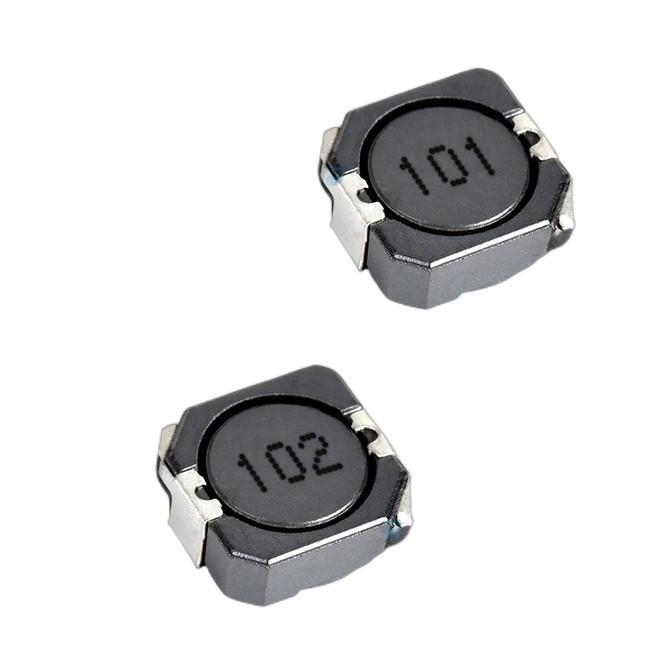
SMD Shielded Power Conductor Structure:
1. Magnetic core: It is a key component of an inductor and is generally made of magnetic materials such as ferrite. Ferrite has high magnetic permeability, which can effectively gather and guide magnetic fields, enhancing the electromagnetic performance of inductors. The shape and size of the magnetic core are designed according to the specifications and application requirements of the inductor, commonly in the form of blocks or rings. It provides a path for magnetic field lines in the winding, helping the inductor store and release energy.
2. Winding: It is made of metal wires (usually copper) and plays a role in conducting current. The number of turns, wire diameter, and winding method of the winding have a significant impact on the performance of the inductor. The number of turns determines the size of the inductance, while the wire diameter affects the current carrying capacity and DC resistance of the inductance. For example, a thicker wire diameter can reduce DC resistance, decrease energy loss when current passes through, and improve the efficiency of inductance. The winding methods include single-layer winding, multi-layer winding, etc. Different winding methods can affect the distributed capacitance and leakage inductance parameters of the inductor.
3. Shielding layer: This is an important structure that distinguishes surface mount shielded power inductors from ordinary inductors. The shielding layer is usually made of magnetic or metallic materials and wrapped around the windings and magnetic cores. Its function is to limit the magnetic field generated by the inductor within a certain range, reduce the radiation of electromagnetic interference (EMI) to the surrounding space, and also prevent external magnetic fields from interfering with the internal magnetic field of the inductor, thus improving the electromagnetic compatibility of the inductor.
4. Solder pad: located at the bottom of the inductor, used to solder the inductor onto a printed circuit board (PCB) to achieve electrical connection with the circuit. The design of the solder pads must comply with the soldering process requirements of the PCB, ensuring good electrical conductivity and mechanical stability between the inductor and the circuit board.
TYPE | DIMENSIONS | INDUCTANCE | |||
Unit | A1(±0.3) | A2 (± 0.3) | B (MAX) | ||
SMRH73 | mm | 7.3 | 7.3 | 3.8 | 10μH~1000 μ H |
inch | 0.2874 | 0.2874 | 0.1496 | ||
SMRH74 | mm | 7.3 | 7.3 | 4.5 | 104μ H-1000μ H |
inch | 0.2874 | 0.2874 | 0.1772 | ||
SMRH124 | mm | 12 | 12 | 5 | 3.9 μ H~330 μ H |
inch | 0.4724 | 0.4724 | 0.1969 | ||
SMRH125 | mm | 12 | 12 | 6.2 | 1.3μH~1000μ H |
inch | 0.4724 | 0.4724 | 0.2441 | ||
SMRH127 | mm | 12 | 12 | 8 | 1.2μH~1000μ H |
inch | 0.4724 | 0.4724 | 0.315 | ||
SMRH103R | mm | 10 | 10 | 3.1 | 0.8μH~150 μ H |
inch | 0.3937 | 0.3937 | 0.122 | ||
SMRH104R | mm | 10 | 10+0.5/-0.3 | 4.2 | 1.5 μH~330 μ H |
inch | 0.3937 | 0.3937 | 0.1654 | ||
SMRH105R | mm | 10 | 10+0.5/-0.3 | 5.1 | 1.5 μH~330 μ H |
inch | 0.3937 | 0.3937 | 0.2008 |
1. Improve circuit performance: In circuits such as switching power supplies, energy storage and conversion can be efficiently carried out, improving power conversion efficiency, reducing output voltage ripple, and providing stable DC power for loads. At the same time, its good electromagnetic compatibility can reduce noise interference in the circuit, improve the performance and reliability of the entire circuit.
2. Easy to automate production: The surface mount packaging form facilitates the use of automated surface mount technology (SMT) for large-scale production, improving production efficiency and reducing production costs. Compared to traditional plug-in inductors, surface mount inductors are more precise and fast in the soldering process, reducing errors and uncertainties caused by manual operations.
3. Adapt to harsh environments: Due to the protection of the shielding layer, the surface mount shielded power inductor can to some extent resist the impact of external environmental factors (such as moisture, dust, etc.) on its performance. In addition, its compact structure and good mechanical stability enable it to maintain stable performance even in vibration and impact environments, making it suitable for various complex application scenarios.
Features | Descriptions |
Compact Size | With surface - mount device (SMD) packaging, it has a small volume, effectively saving printed circuit board (PCB) space. This meets the design requirements of miniaturization and lightweighting of electronic products, facilitating the integration of more components in a limited space. |
Good Shielding Performance | Equipped with a shielding layer, it can significantly reduce the radiation and reception of electromagnetic interference (EMI). On one hand, it prevents the magnetic field generated by itself from interfering with surrounding sensitive circuits. On the other hand, it resists the influence of external magnetic fields on the inductor's performance, improving the stability and reliability of the circuit. |
High Power - handling Capacity | It can withstand large currents and is suitable for power conversion circuits, such as switching power supplies. By using a thick - wire - diameter winding and a low - DC - resistance design, the heat loss during current passage is reduced, ensuring stable operation under high - power conditions. |
High - precision Inductance Value | Through precise control of core materials, winding turns, and winding processes, a high - precision inductance value can be achieved. This meets the requirements of circuits with strict demands for inductance values, guaranteeing the consistency and stability of circuit performance. |
Low DC Resistance | The winding has a low DC resistance, which can reduce the power loss when current passes through. Less energy is dissipated in the form of heat, improving the efficiency of the inductor, especially suitable for circuits with strict power consumption requirements. |